Pressure Transducer Amplifier
Client:
Sensortech LLC
Competencies:
Embedded Firmware Design
Digital Filter Design and Analysis
Creating a Transducer Amplifier for an Unusual Strain Gage Polymer Material
A medical device company had an idea for a novel way to measure pressure on the end of a prosthetic limb so it could be fit better: Put a polymer sheet in the junction between a prosthetic and an amputated limb and measure resistivity in x- and y- across the sheet (doing some deconvolution along the way) as the sheet gets thinner and deforms, lowering the local resistance. This was a complex enough problem that before tackling it, the medical company elected to build a simple strain transducer in one axis, and they contracted that work out to somebody other than us.
Unfortunately, the people who did the work didn’t understand the concepts of spectrally pure sampling or that analog inputs to systems have to be lowpass filtered. So it fell to us to figure out how to lock A-to-D conversions to a hardware timer doing minimal rework to the incorrectly wired PCB with which we had to work. We also had to turn the entire software structure on its head, since it had been written with the display driver getting primacy. And for proper sampling and running a lowpass filter, dealing with signals in the tens of kilohertz were far more important than dealing with what the human eye with its 30Hz resolution could perceive.

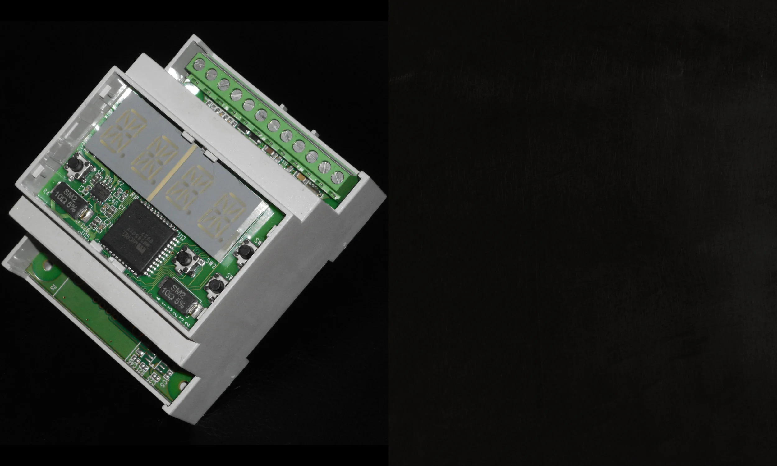
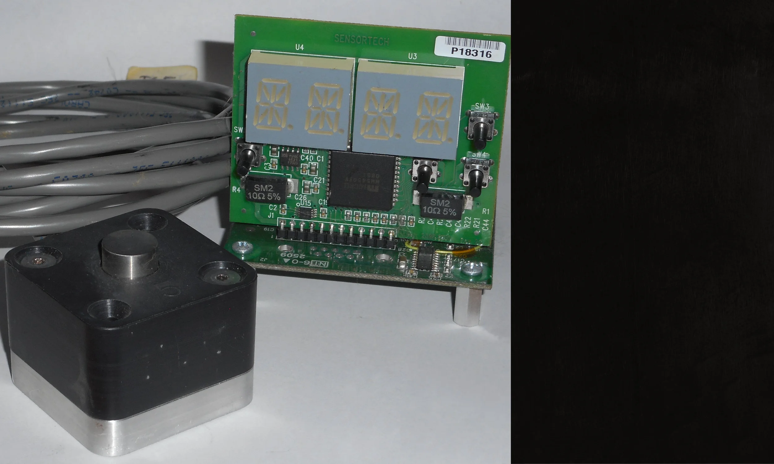
The sensor (pressure) transducer at lower left and the instrumentation package that read it at upper right.
What We Did: Coding Somebody Else’s Hardware when it was Full of Bugs.
The previous author of the software used in the amplifier system was fascinated with driving an alphanumeric display. So fascinated, in fact, that he made driving it the top priority of his code and he took a few A-to-D readings on the transducer when he got around to it. And he started the ADC in software every time, so the space between readings was completely non-deterministic. The result? ADC data that were completely unusable.
We recognized — mostly from our experiences designing Picoprojectors — that the human eye and brain are enormously forgiving and that you can still run scanned, multiplexed display elements at low (and non-deterministic) speeds and satisfy a user’s visual cortex. So we flipped the code structure and attached the start signal of the ADC to a hardware timer internal to the processor chip. Suddenly, we were getting spectrally pure data and could generate real results. We only had to figure out the least intrusive way to lift a pin and add a wire to the processor to get at that hardware signal we needed. In the first round, the number of units shipped would be small, and nobody could justify redoing the entire PCB layout.
What We Did: Checking Latency and Phase Lag After Adding Digital Lowpass Filtering
By the time we inherited the project, one thing that had never been done was an end-to-end check of system latency, probably in part because ADC sampling in the original design was so non-deterministic that it couldn’t be measured if anyone tried. When we got the ADC locked on a hardware timer, sample windows were spaced with minimal jitter, and the results were bereft of most of the prior high-frequency trash created by the sampling method itself.
The previous firm had done poor lowpass filtering of the ADC input as well, so it fell to us to do some digital lowpass filtering — which introduces a phase delay of its own. So when we got the system right side up, we had two things to analyze and measure: Latency introduced by the time required to complete the ADC conversion itself plus phase shift of a moving average FIR digital lowpass filter.
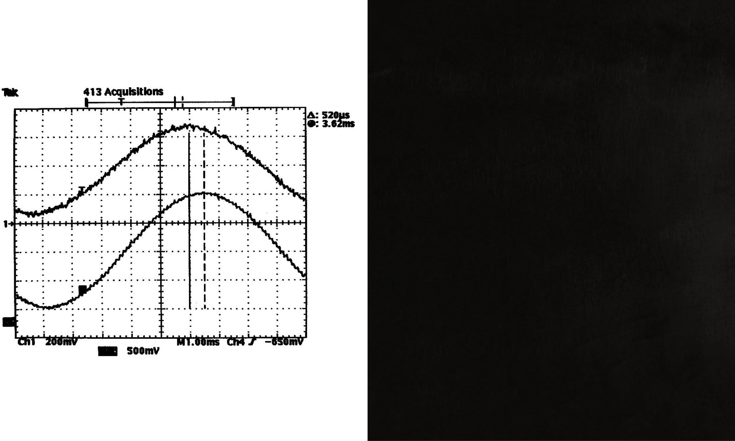
Below is a representation of the (noisy) input signal at top and the filtered and delayed (by 520 microseconds) output at bottom. Critically, the wave shape is undistorted, indicating that at least at the frequencies of interest, sampling is happening on repeatable intervals.

Digital lowpass filtering added a perfectly acceptable 520 microseconds of phase lag to the signal chain overall.
What We Did: Analysis of the Digital Lowpass Filter
Critical to making the entire system work was an effort to analyze properly the digital finite impulse response lowpass filter we had to create: How big a circular buffer we’d use and how we’d weight current and past samples (and where the weighting factor would go to zero so the impulse response would be zero).
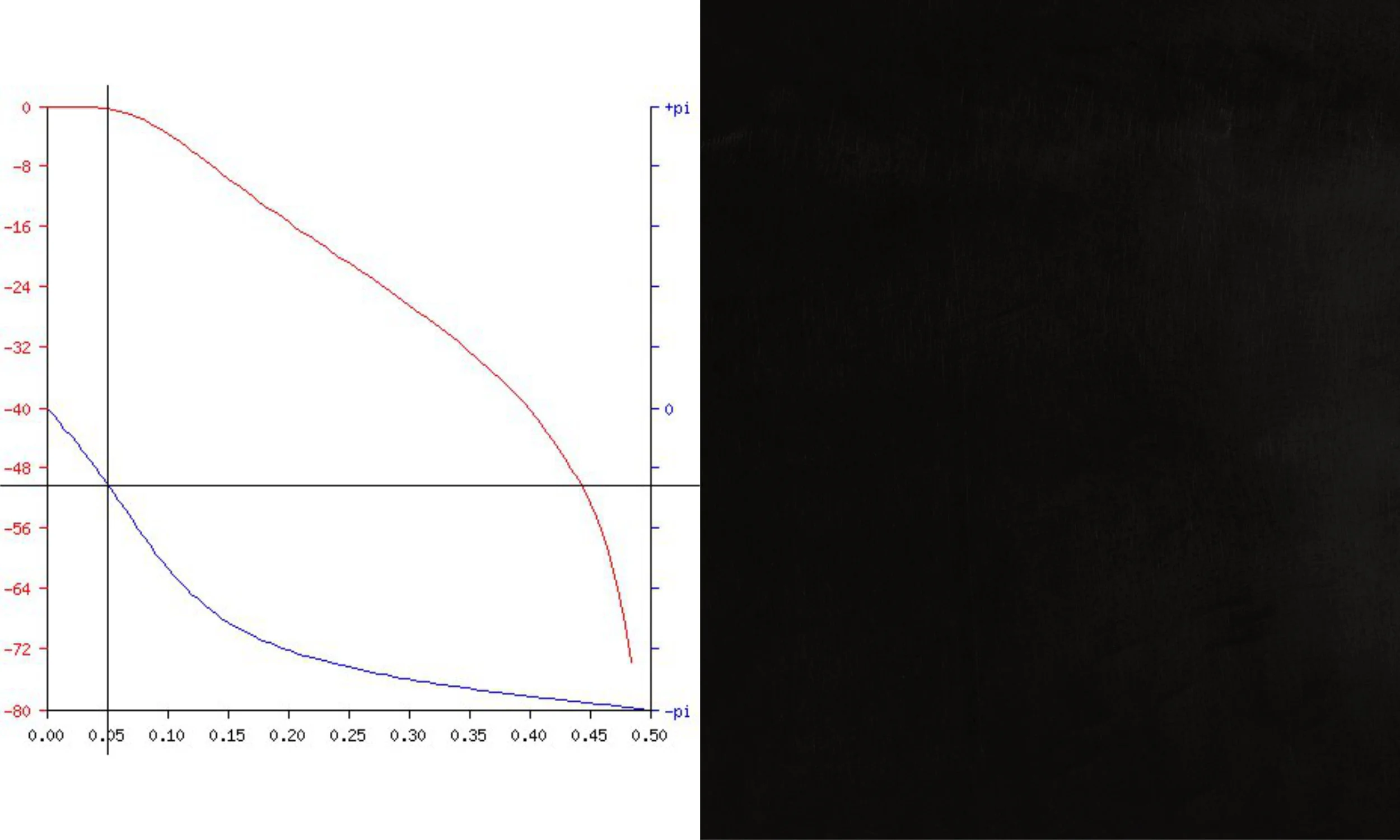
As shown below by the upper line (amplitude), by the time we were at the -3dB point of the filter, we were at roughly 1/4 pi (45 degrees) phase delay as we would expect.
This is at least some of the delay visible in the oscilloscope trace above.

What We Did: Finding the Minimal Number of Fixes Required to the PCB
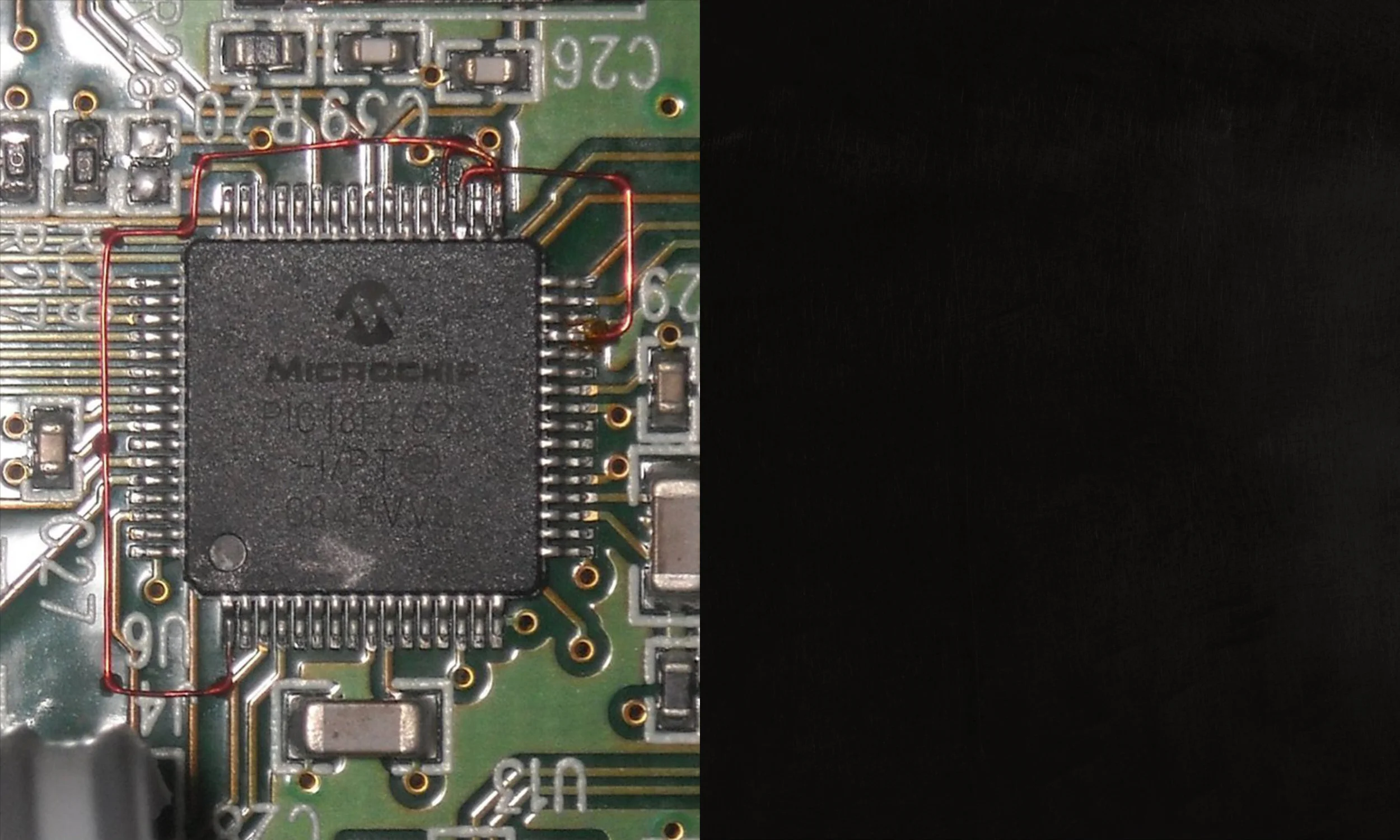
The end customer had already had a number of PCB’s built to the previous design house’s buggy design specs. The single biggest problem was that the microcontroller chosen (a Microchip PIC18) has counter-timers internally that would have been suitable for driving the A-to-D converter, but those signals are also connected to pins on the chip to which the previous designers had already wired external circuits. Our task then became figuring out how to do the minimum amount of rework required to get the external signals off these pins (and into other pins on the chip where they could still be seen) so that the critical counter-timer resources didn’t have things in the way. In the end, we got it down to two wires to get the ADC “Start” and ADC “End of Conversion” signals freed from external signals that would back-drive them. For the original 50-100 PCB’s the end customer had bought, this was an acceptable patch while the PCB got redone to our specifications.

Magnet wire added to a few lifted processor pins in order to rewire things such that critical I/O signals weren’t blocked. The errors in the hardware were ones we inherited. In a later revision of this card, we corrected the previous shop’s mistakes.