Weightlifting Coach
Client:
Holness Intellectual Property
Competencies:
Embedded Controller Hardware Design
Embedded Controller Firmware Design in C and Assembly Language
PCB Layout
Mechanical Design for an Optical System
An Electronic Coach for Your Weightlifting Workout
Our customer held patents in the sporting goods field, and he wanted his claims and concepts brought fully to life.
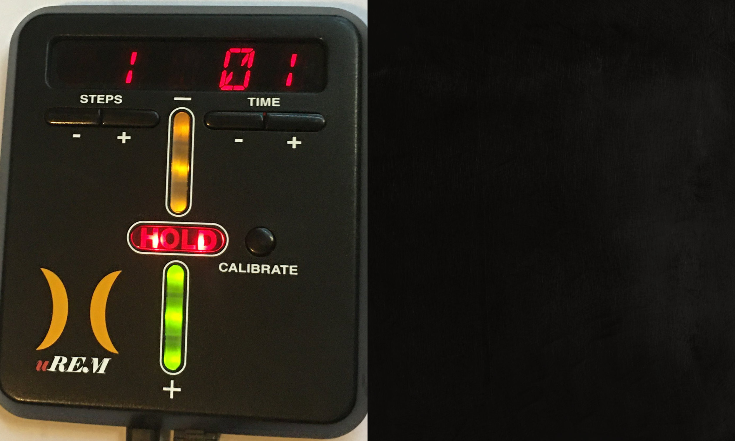
As an expert on biomechanics, he knew that one of the most effective ways to build muscle is to stop a lift in mid-stroke and hold the weight for a period of time before resuming. And his vision was for a device that with a bar of green LED’s could show how much further to push the weight up (or with a bar of yellow LED’s to show how much to let it back down). The user would be allowed to set how many “steps” or stopping points there would be. And every time the weight got to a stopping point, the “HOLD” light would tell the user to hold the weight in place there while a timer that the user could set would count down the time to hold it.
Our job was to build the instrument with the display, set up a timer circuit inside it, and come up with a way to measure the up-and-down of the weight stack — keeping track of which direction it was going at all times.

What We Did:
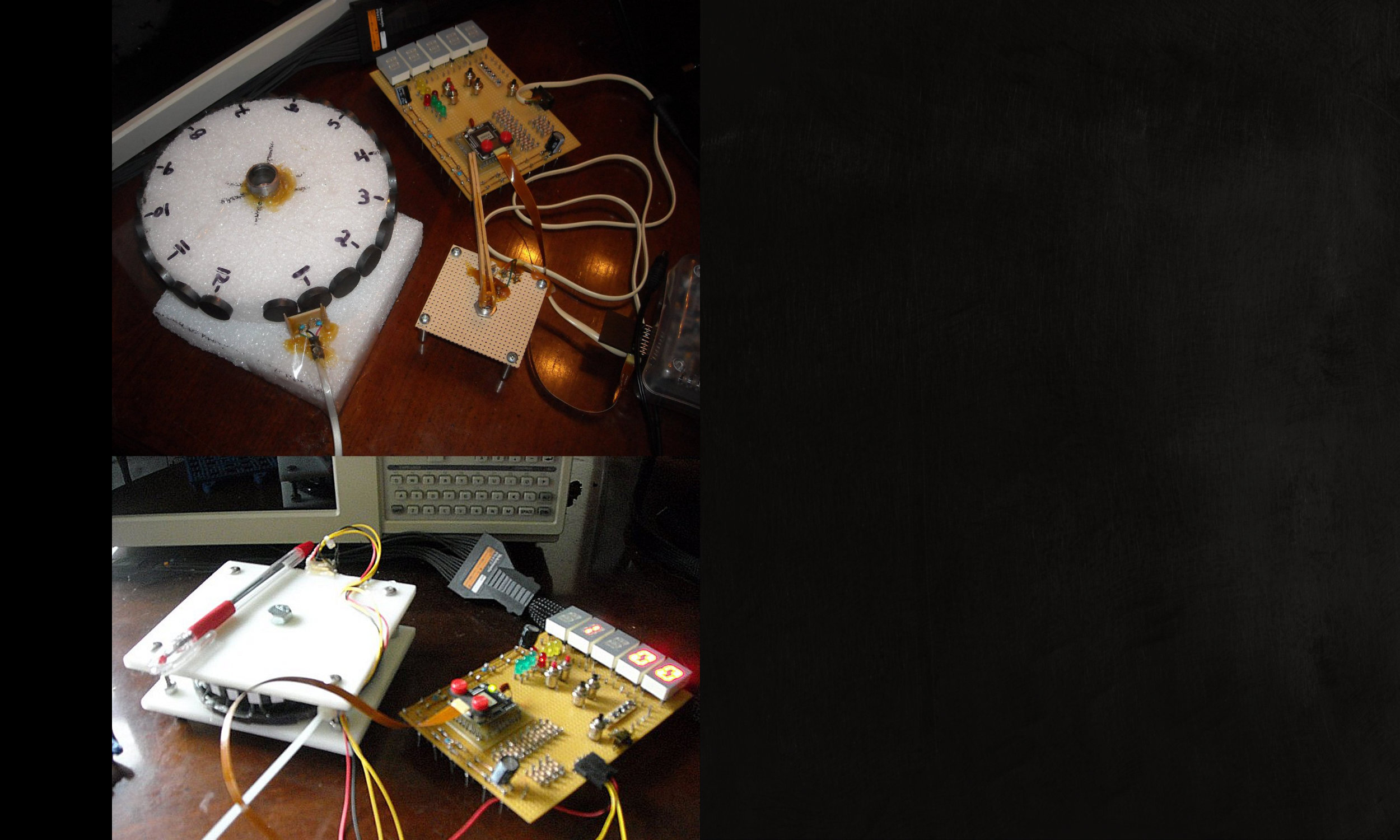
Because this was before the days of cheap LIDAR (which is the technology we’d use now if we had the project to do over), our plan was to use either slotted optical switches or magnets (placed near Hall-effect sensors) on a pulley wheel attached to the weight stack.
We tried both approaches and concluded that a weightroom environment was low enough in dust usually that an optical approach would be easier to implement.
But along the way, we’d made styrofoam wheels with magnets glued to them as well as wheels with alternating black-and-white regions that a reflective photodiode-LED combination could see.
In the end, in cooperation with our mechanical engineering partners on the project, we concluded that a transmissive optical switch and a slotted wheel would be the most reliable approach.
Ah, to have had one of the short-range semiconductor LIDAR chips on the market today…
What We Did: In Phase and Quadrature Measurement
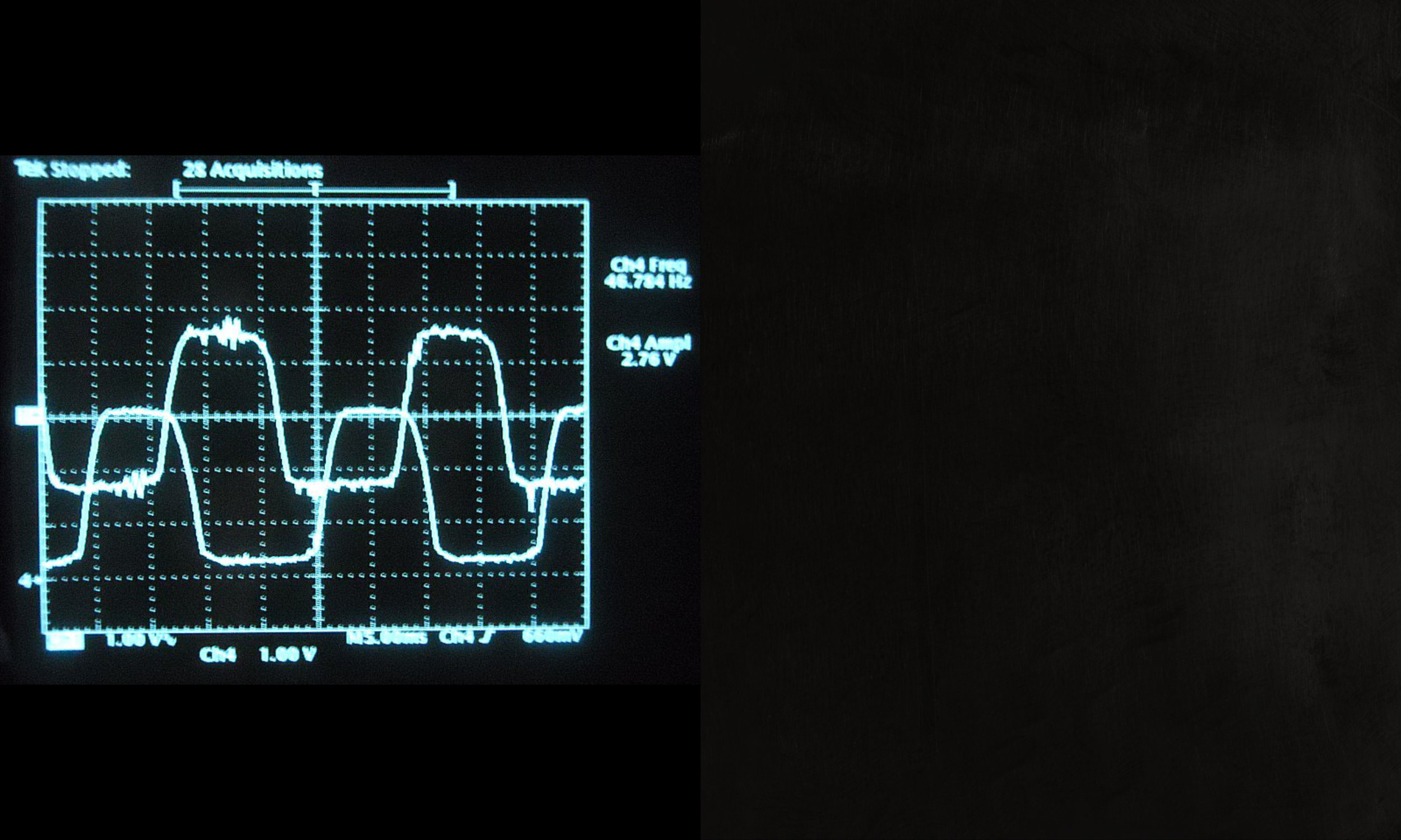
With a train of pulses, you can tell how far something moves. But you can’t tell in which direction it’s moving. That you can only determine with two trains of pulses — one leading and one lagging — spaced by 90 degrees. When we got our mechanicals figured out such that the size and spacing of the slots in the slotted wheel lined up to generate “in-phase” and “quadrature” signals, it took a few bits of sleight-of-hand both to count the pulses and figure out which was “ahead” and which was “behind” so we knew which way the wheel was spinning. At left is an example of the two pulse trains as seen on an oscilloscope screen.

What We Did: The Displays
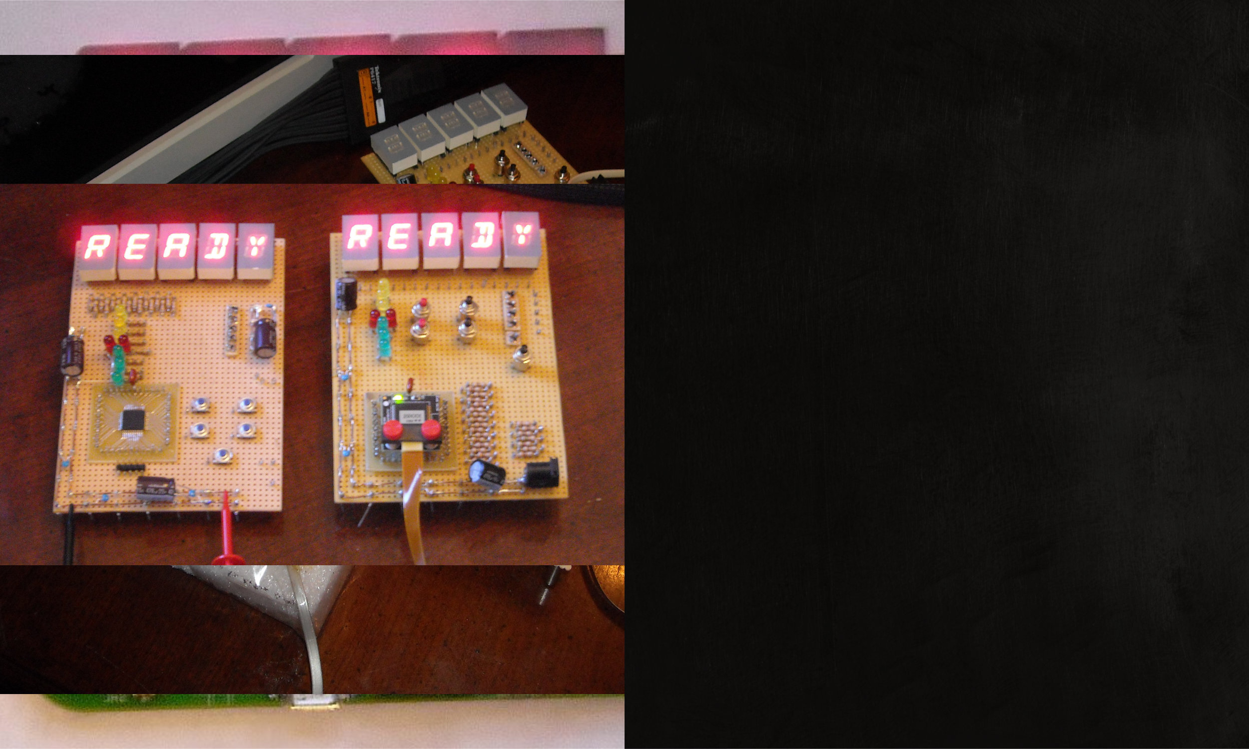
Clearly we had a user with whom we had to interact. And to do so, we needed an alphanumeric display, LED’s to show progress, and a few input buttons. We mocked up the buttons two different ways to see what might make more sense — and ultimately concluded that the best solution was something unlike either mockup. On one mockup (the one on the left here), we soldered an actual microprocessor chip. To the other (the one on the right here), we attached an in-circuit emulator so we could run software from a host PC and see how the system behaved.
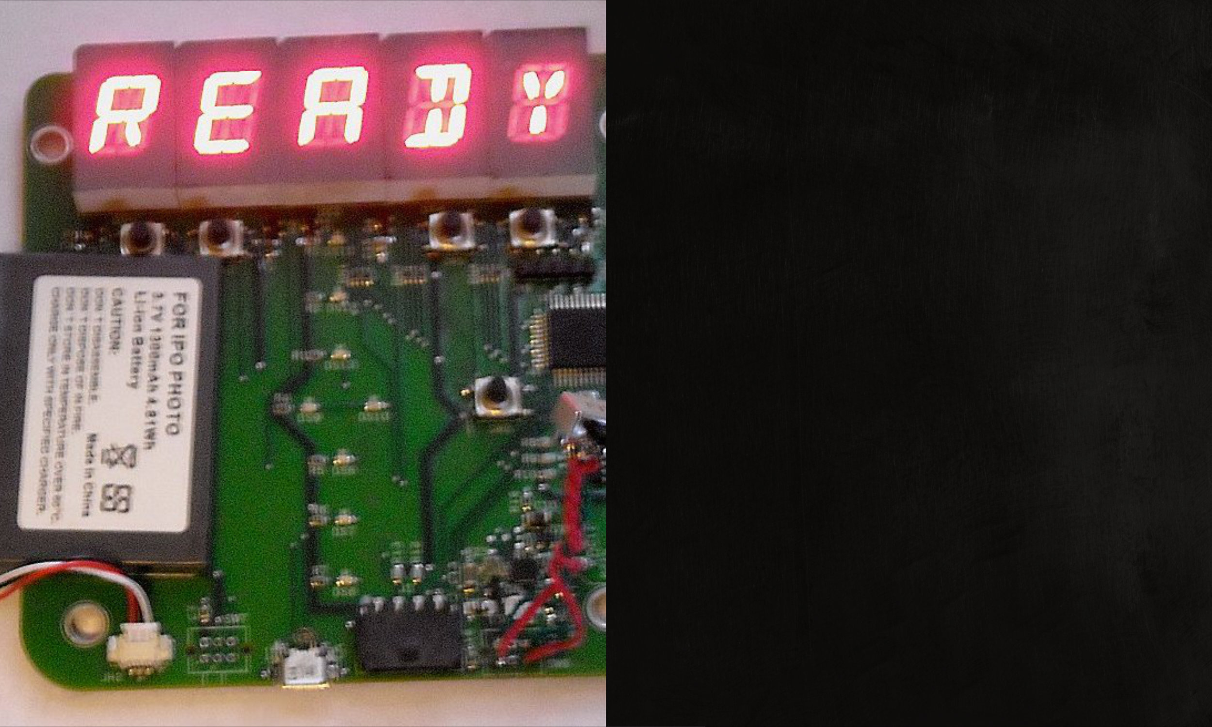
Note that this photo is slightly fuzzy because it was taken at extreme low speed. This was necessary since not all the display segments in “READY” seen here are lit at once. The microprocessor just didn’t have enough pins on it to drive five complete alphanumeric displays, and the current draw of all of them being lit at once would drain the battery in the system pretty quickly. So we only wrote one letter at a time, wrote the next, and so on — and cycled around the five letters/numbers so quickly that persistence of vision made it look like everything was lit at once.

What We Did:
With all of the complexity of measuring pulses, running timers, and driving display LED’s behind us, the final task was to devise a way to power the entire thing from a rapidly chargeable Li-ion battery that could get its recharge power from a USB port.
And with that accomplished, we put it all on a PCB for mass manufacture and sent it out into the world.